top of page
Innovating For Tomorrow
Cooke Inc.


Schematic
Schematic & Board Layout
The schematic is broken into parts far left power supply related, middle is function generator related, and far right is headers to the pinout on the Freedom board.


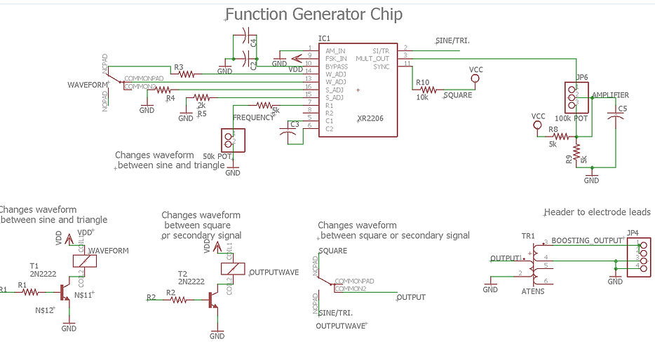
This is the heart of the unit. Middle top is the function generator chip, connected to it are two variable resistors at pins 3 and 7. Pin 3 controls the amplitude, and pin 7 controls the frequency of the output. Attached to pin 13 is a relay when energized turns the output at pin 2 into a sine wave when not energized it is a triangle wave. There is also a second relay which switches the output between a square wave and the outputting signal of pin 2. The output of the second relay is then inputted into the boosting circuit.
The power comes in from 12V source which is connected to the 120V AC line. Then goes through a single pole single throw switch where it is then tapped off of to power the function generator I.C. circuit. A capacitor is placed across the 12V the supply in order to filter some of the noise. Power is also brought to a LM7805 to be stepped down to 5 volts.
The LCD and microcontroller are powered off the 5V supply. The pin selection was chosen based on ease of routing, coding and easy access of the power/ground pins on the Freedom Board.
Power Source
Function Generator
Headers
Board
bottom of page